A flange bolting procedure specifies the tightening sequence, number of passes and torque values applied to each bolt when assembling a flanged joint. Under ASME PCC-1, the standard method is a cross-pattern (star pattern) sequence across three or more passes at progressively increasing torque, with bolt schedule, gasket type, lubricant and tool calibration documented at each pass.
Uneven bolt loading, skipped passes and incorrect cross-patterns account for most flange leaks in process industries. Get any step wrong on a pressure-boundary joint and the failure is rarely the bolt itself, it is the procedure.
Why the tightening sequence matters
When you tighten a bolt on a flanged joint, you compress the gasket locally. But that compression also affects the load on adjacent bolts. Tightening bolts sequentially around the flange, one after another, creates uneven gasket compression. One side of the gasket bears too much load while the opposite side remains under-compressed. The result is a joint that leaks under pressure or temperature cycling.
A cross-pattern sequence distributes the compressive load more evenly across the gasket face. By tightening bolts on opposite sides of the flange alternately, each pass brings the gasket closer to uniform compression. This is the fundamental principle behind every credible flange bolting procedure.
The standard cross-pattern sequence
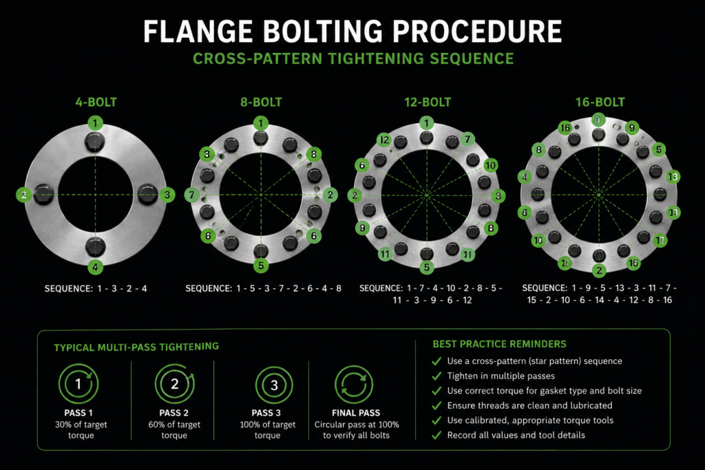
For a circular flange with evenly spaced bolts, the cross-pattern works as follows. Number each bolt position starting from any point. Tighten bolt 1 first, then move to the bolt directly opposite (bolt 2). Then move 90 degrees to bolt 3, and across to its opposite at bolt 4. Continue this pattern until every bolt has been tightened.
For common flange sizes, the sequences look like this.
4-bolt flange: 1, 3, 2, 4 (opposite pairs).
8-bolt flange: 1, 5, 3, 7, 2, 6, 4, 8.
12-bolt flange: 1, 7, 4, 10, 2, 8, 5, 11, 3, 9, 6, 12.
16-bolt flange: 1, 9, 5, 13, 3, 11, 7, 15, 2, 10, 6, 14, 4, 12, 8, 16.
For larger flanges with 20, 24, or more bolts, the same principle applies. Always tighten the bolt furthest from the last one tightened. ASME PCC-1 provides detailed bolt-pattern diagrams for standard configurations.
Multi-pass tightening: how many passes and at what values
A single pass to final torque will not produce a reliable joint. The gasket compresses and relaxes as adjacent bolts are loaded, meaning the first bolts tightened in a pass lose some of their initial load by the time the last bolt is tightened. Multiple passes compensate for this interaction, commonly called elastic interaction or bolt relaxation.
A proven approach uses a minimum of three passes.
Pass 1: Tighten all bolts to approximately 30% of the target torque in the cross-pattern sequence. This seats the gasket and brings the flange faces into initial contact.
Pass 2: Increase to approximately 60% of target torque, following the same sequence.
Pass 3: Tighten to 100% of target torque in the same cross-pattern.
Final pass: A circular pass (sequentially around the flange) at 100% to verify all bolts are at the final value.
Some specifications call for four or five passes. The principle remains the same: incremental loading in a controlled sequence.
Common flange bolting mistakes
Skipping the first pass. Going directly to 50% or higher on the first pass risks cocking the flange, particularly on raised-face flanges with spiral-wound gaskets. A low initial pass keeps the flange faces parallel.
Incorrect sequence on non-standard flanges. Rectangular flanges, heat exchanger channel flanges, and non-circular joints require adapted sequences. The cross-pattern principle still applies, but the bolt numbering and opposite-pair logic changes. Consult the specific joint drawing.
Ignoring bolt condition. Corroded, galled, or dry threads change the friction coefficient and invalidate the torque-to-load relationship. Clean threads and apply the lubricant specified in the procedure before assembly.
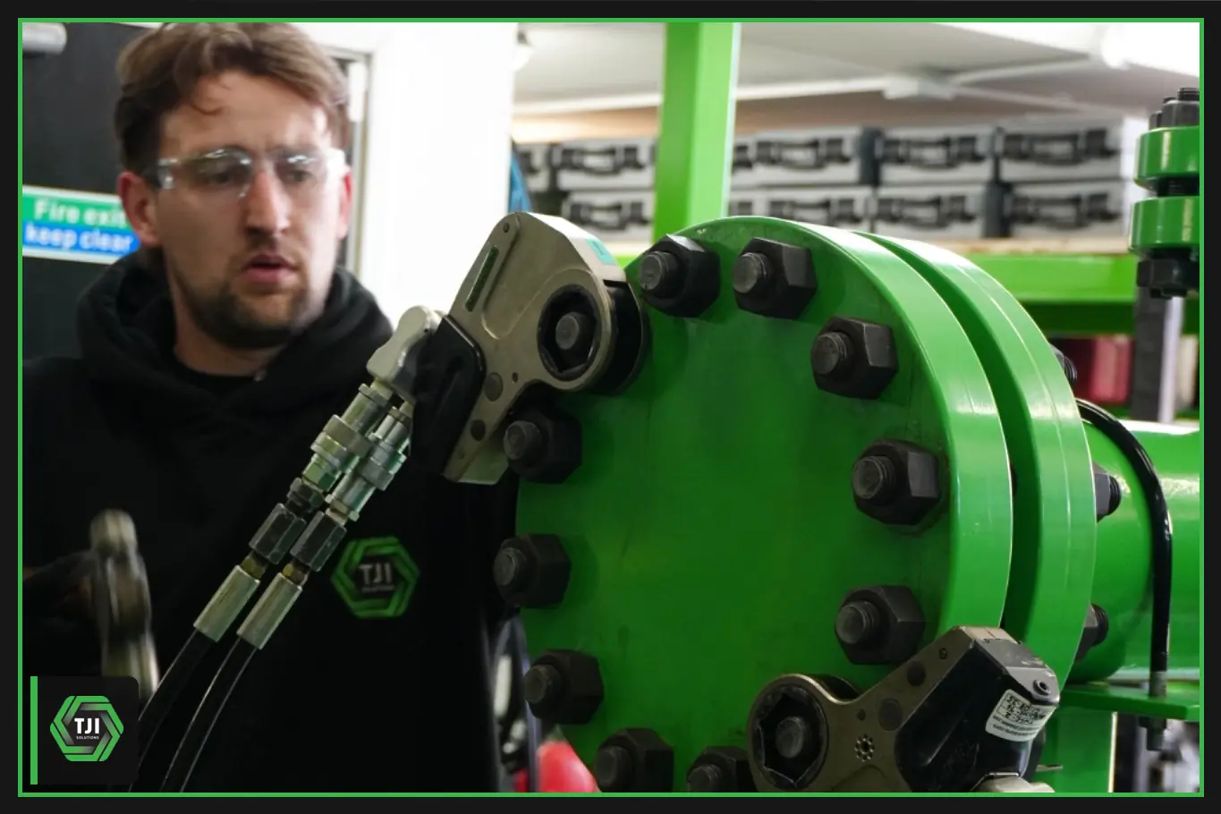
Using the wrong tool for the torque range. Manual torque wrenches become impractical and inaccurate above approximately 400 Nm. For large-bore flanges requiring 1,000 Nm or more per bolt, a hydraulic torque wrench provides the accuracy and repeatability needed. TJI supplies hydraulic torque equipment for hire alongside nut splitters and flange spreaders for the full flange maintenance workflow.
Gasket type affects the procedure
Different gasket materials respond differently to bolt load. Spiral-wound gaskets with a metal winding and filler material can tolerate higher compressive loads than soft-cut gaskets. Ring-type joint (RTJ) gaskets, which are solid metal, require significantly higher bolt loads to achieve a seal.
The procedure must account for the gasket type. Over-compressing a soft gasket crushes it beyond recovery. Under-compressing a spiral-wound gasket leaves gaps in the seal. The target bolt load, and therefore the torque value, should be calculated based on the gasket manufacturer’s recommended seating stress, not simply pulled from a generic table.
Inspect the gasket and flange faces before assembly. A scratched or pitted flange face or a damaged gasket will not seal regardless of how carefully you follow the tightening sequence.
Recording and documentation
Every flange joint assembly should be documented. Record the bolt sequence used, the torque values applied at each pass, the gasket type and condition, the lubricant used, and the tool identification number with its calibration certificate reference.
This documentation is a requirement under ASME PCC-1 for pressure boundary joints and is increasingly expected by asset owners and inspection authorities across oil and gas, petrochemical, and power generation sectors.
If you are assembling critical flanged joints and need equipment, guidance, or torque tool hire for an upcoming shutdown or maintenance scope, speak to TJI’s technical team about matching the right tools to your bolt schedule.